Input : I2S, bitdepth from 16 to 32 bits, sampling rate upto 768khz,
Asynchronous FIFO built-in,
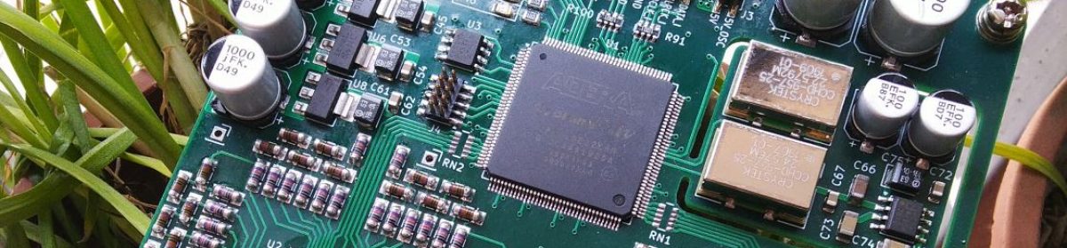
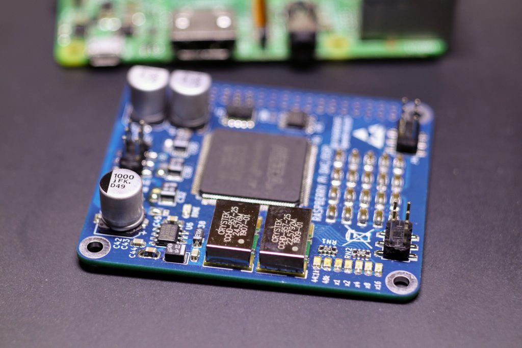
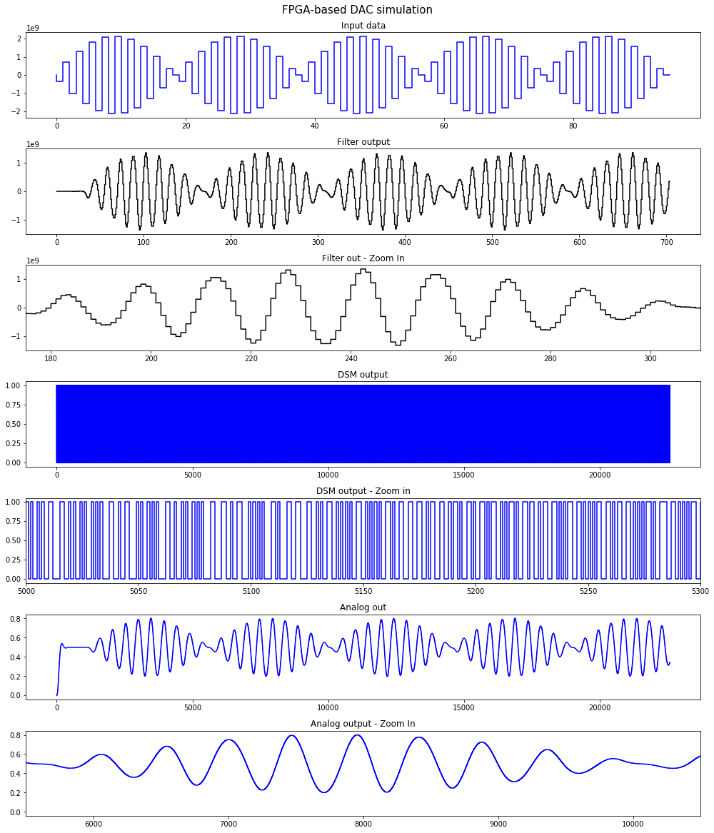
FPGA-based delta-sigma digital to analog converter (DAC),
256-step digital volume,
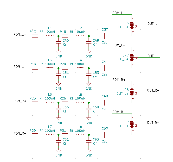
Full balanced outputs,
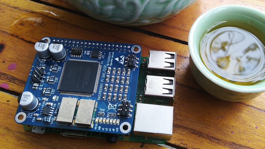
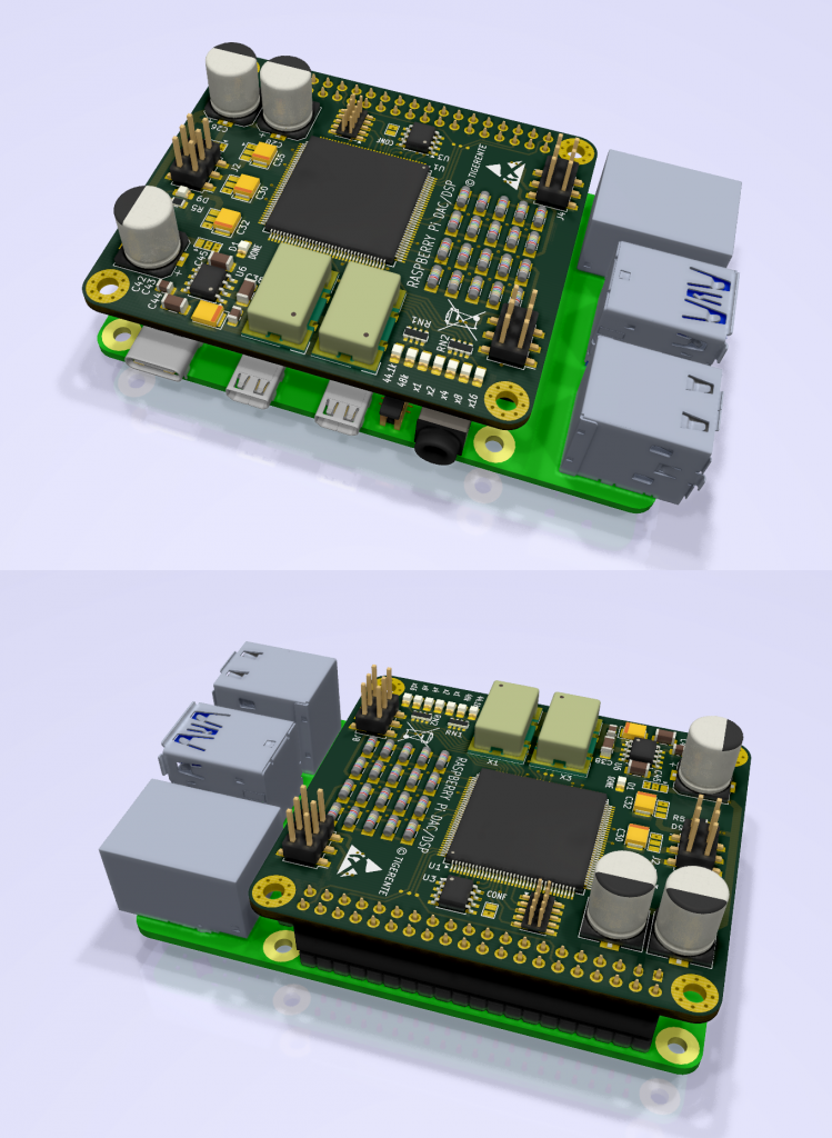
Compatible with Raspberry Pi 3/3B+/4 connection,
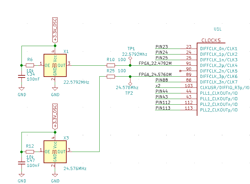
Ultra-low phase noise oscillators with high precision linear low drop voltage regulators are designed specifically for High-Definition audio (HD audio).
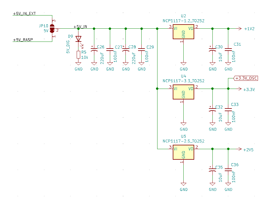
Schematic and PCB design
Schematic and PCB were designed using Free open software KiCad
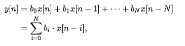
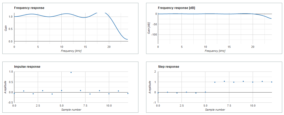
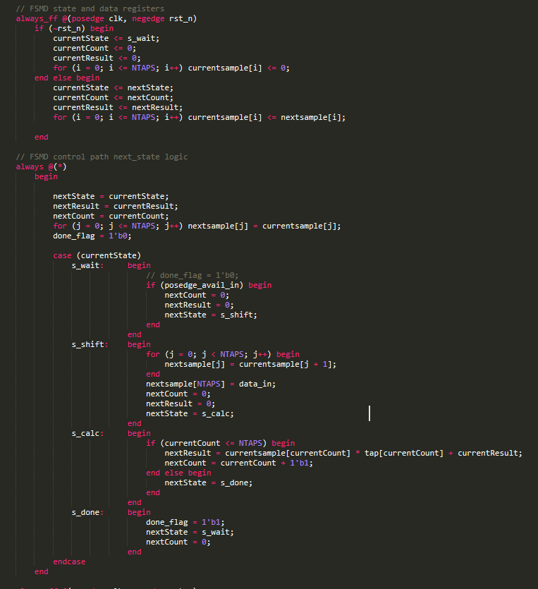
Finite impulse response (FIR) filters are characterized by the fact that they use only delayed versions of the input signal to filter the input to the output. For a causal discrete-time FIR filter of order N, each value of the output sequence is a weighted sum of the most recent input values:
Where:
x[n] is the input signal,
y[n] is the output signal,
N is the filter order
bi is the value of the impulse response, also a coefficient of the filter
Filter design
FIR filter designing is finding the coefficients and filter order that meet certain specifications. When a particular frequency response is desired, several different design methods are common:
Window design method
Frequency sampling method
Least MSE (mean square error) method
Parks-McClellan method
DFT algorithms
There many software such as MATLAB, GNU Octave, Scilab and SciPy (Python). In this topic, I only share how to implement FIR filter on FPGA. So the detail of filter designing, finding coefficients will shared in the later topics.
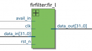
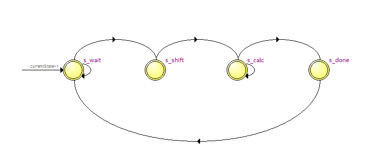
Implementing a FIR filter on FPGA for slow signal
FIR filter for slow signal will designed by using special way to save the number of multipliers.
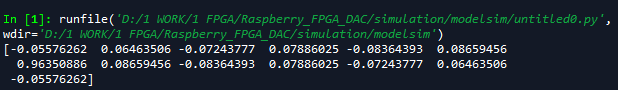
Finding coefficients using window method
Using Python
from future import print_function from future import division import numpy as np
fS = 48000 # Sampling rate. fL = 22000 # Cutoff frequency. N = 13 # Filter length, must be odd.